3 professional tips: This is how form measurement works
Tip 1: Apply correct filters
In order for you to evaluate the measurement data correctly, the selection of the correct filters in the software is an essential prerequisite. However, if an in-house standard or filter settings aren’t provided, we advise the following: First decide which measurement task you want to perform with your form measuring machine - the inspection of surface roughness or a form measurement. If you want to check the surface roughness of a workpiece, use the data with short wavelength for the analysis, while discarding those with long wavelength. For a form measurement, filter and evaluate the data with long wavelength, which refers to the form, and you can discard the data with short wavelength.
However, with the two described measuring tasks, you have to consider further differences. To measure surface roughness, the filter settings are defined in terms of millimeters or inches. For example, if you set the filter to 0.8 mm, this means that surface deviations of less than 0.8 mm are accepted as surface roughness, while elements of more than 0.8 mm are not included in the result.
In contrast, shape filters for roundness measurements, for example, are usually specified as an angular size, but not in angular degrees, rather in a unit known as "waves per revolution" or UPR for short. Many users choose 50 UPR as the default value. This means that the arc length is 1/50 of a circle or a section on the surface of a round object, which corresponds to 7.2 degrees. However, the arc length changes analogously to the diameter of the workpiece.
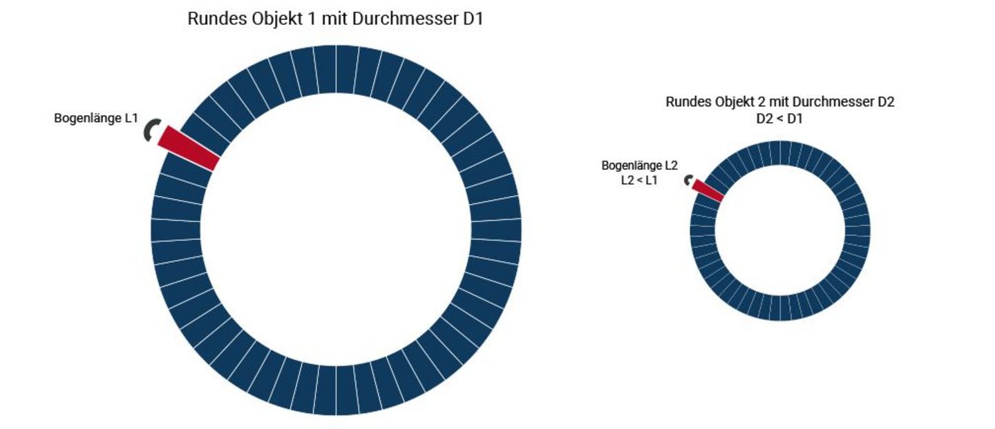
Therefore, you must always select the correct filter depending on the diameter and the subsequent function of the workpiece. Depending on the choice of filter, shape defects can contain only coarse components (workpiece is oval or "three-sided equal thickness") or also finer components such as higher-frequency waviness.
You can obtain further tips on the correct choice of filter depending on diameter and application, for example, in the training courses of the Mahr Academy or during a training session directly at your Mahr formtester.
Tip 2: Choose the right probe size
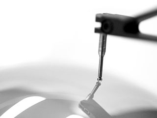
When selecting the probe, you must take into account the dimensions of the component to be tested. This is because the sensing ball at the tip of the sensing element is itself a mechanical filter. The probe must therefore correspond to the workpiece size and the maximum measurable number of waves per revolution. If a probe element that is too large travels on the measuring surface, it cannot optimally plunge into all valleys of the real profile. As a result, the unsuitable probe causes unwanted mechanical filtering of the data, which falsifies the measurement results.
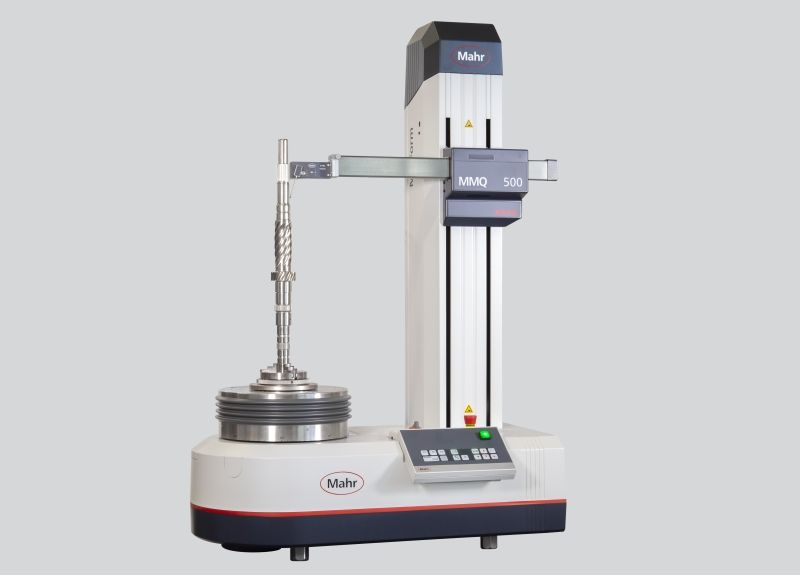
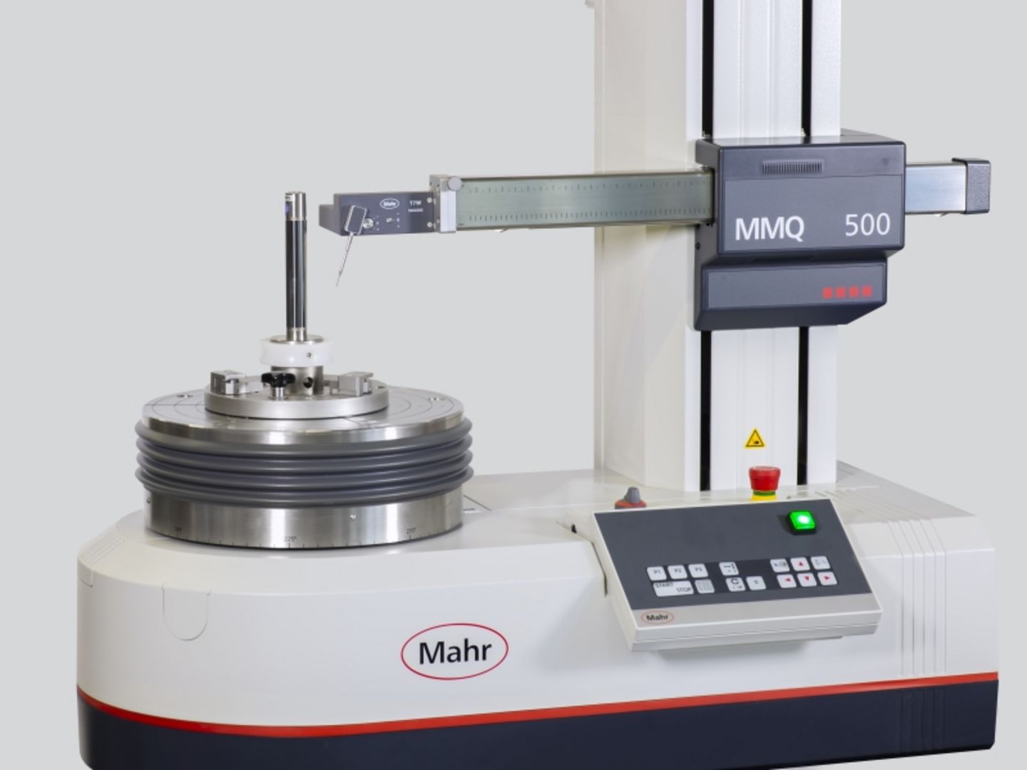
Incidentally, the VDI/VDE Society for Measurement and Automation Technology can advise you on the selection criteria for the correct probe element: its guideline VDI/VDE 2631 "Form Measurement Basics" sheet 3 contains a guide on how to select and use the correct probe element. With the MarForm MMQ 500, the use of the correct probe element is very convenient: Its probe arm unit holds up to four probe arms at once and changes them quickly and fully automatically depending on the measuring task and without any operator intervention.
Tip 3: Align workpiece precisely
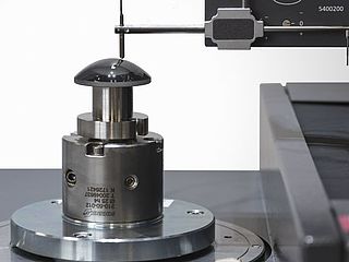
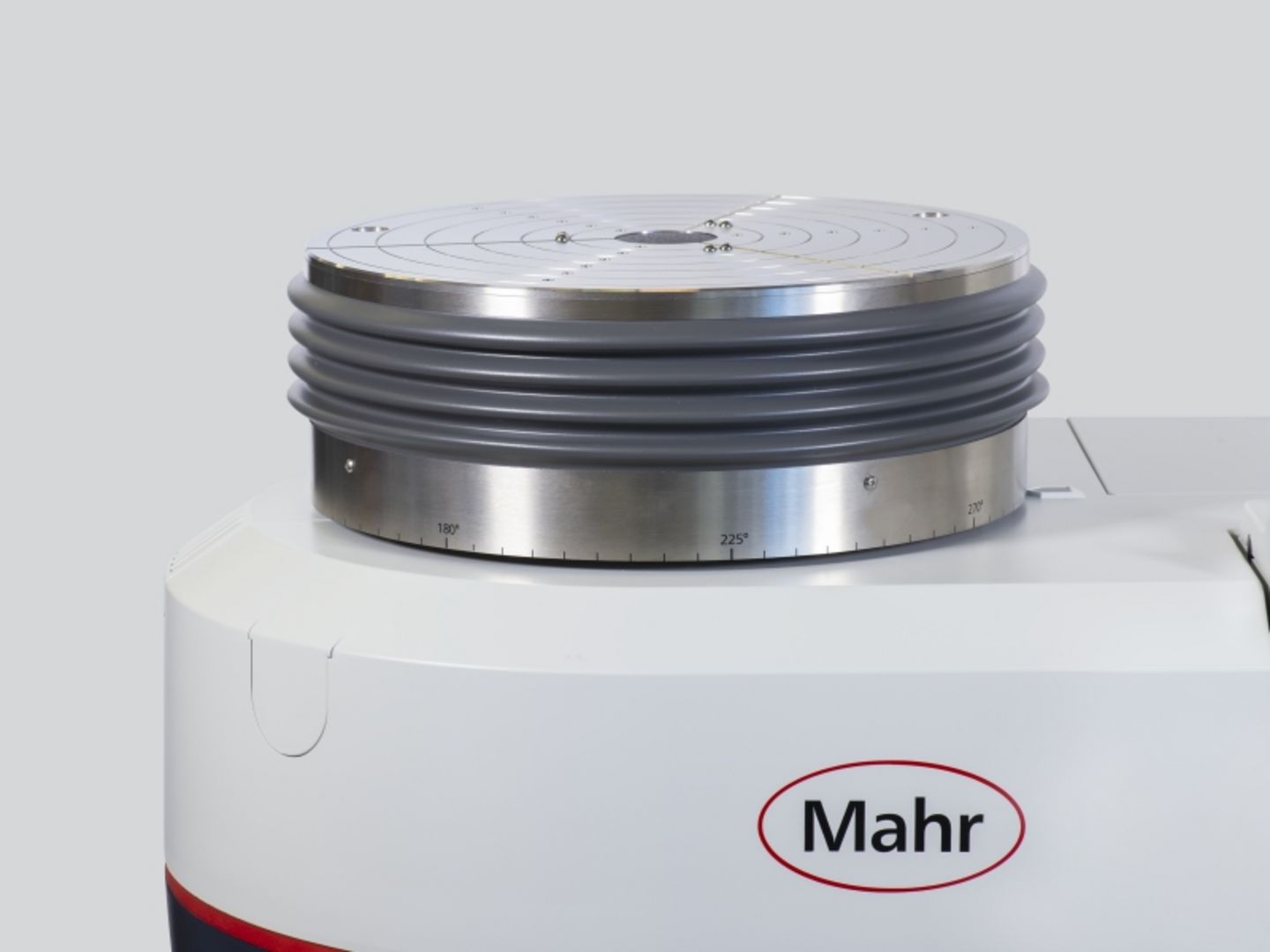
Before you can measure the form and position characteristics of a workpiece with a formtester, you must first align it: With the help of the tilting and centering table, you tilt and center it so that the axis of the workpiece and the axis of rotation of the formtester coincide. This prevents you from measuring supposed shape defects that are not there. For example, if the alignment is incorrect, a cut through an inclined cylinder may incorrectly show up as an ellipse rather than a circle. In addition, correct alignment prevents the probing point, which ideally lies exactly in the X-Z plane, from wandering during the measurement.
With formtester that have an automatic tilting and centering table, like the MarForm MMQ 500, you can control alignment errors very well: Due to the high precision during alignment, you can neglect contributions to errors in roundness measurement. For example, a typical residual eccentric of 5 µm on a cylinder with an outer diameter of 50 mm leads to an additional roundness deviation of less than one nanometer. For other features, especially those relating to position, or components with small diameters, the influence of alignment errors may be greater. However, it is also true here that you can keep this negligibly small by exact alignment.
In practice, therefore, two fundamental questions arise during alignment:
1. Where, i.e. at which points on the workpiece, should alignment take place?
2. How precisely should the workpiece be aligned?
If a workpiece has a main reference, you should always align to this reference. If there is no main reference, it makes sense to align at the points with the smallest tolerances. It is recommended to limit the skew to ten times the numerical value of the residual eccentric (5 µm residual eccentric at 50 µm/m permissible inclination). Then no problems will arise from the remaining skew, regardless of the distance between the measured circles.
For many measuring tasks, the residual eccentric of 5 µm stored as the default value in the MarWin software is absolutely sufficient. The Mahr formtesters usually achieve this quickly and reliably, so you should not use larger values. For small tolerances (e.g. 1 µm roundness, 5 µm cylindricity or 5 µm concentricity) or for components with small diameters (10 mm and smaller), it is advisable to reduce the permitted residual eccentric. With the new MarForm MMQ 500 formtester, you can align your components reliably and quickly even to the smallest of residual eccentrics.


